

 Dr. Gregg Condon, MMR/photos by the author except as noted
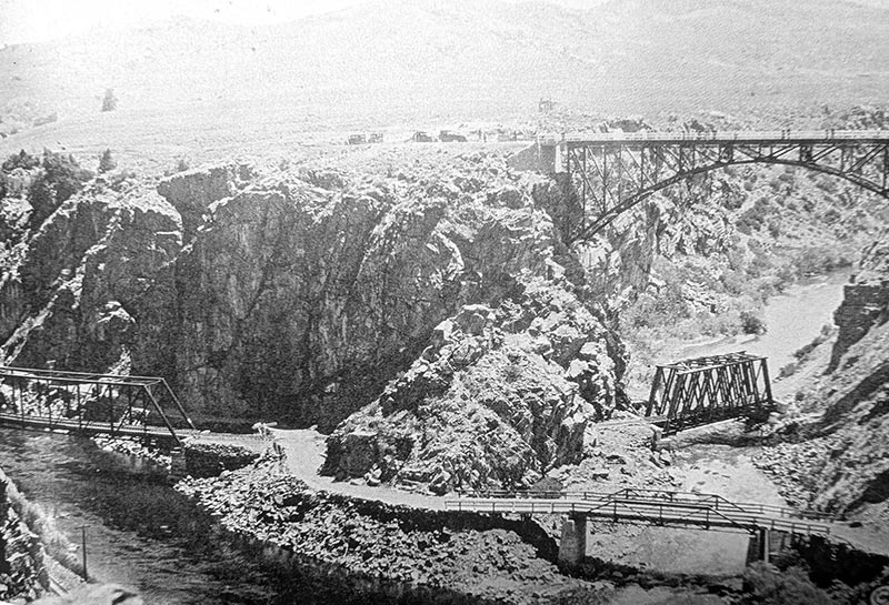
A favorite narrow gauge scene that I always thought would look good on a layout is Lake Junction on the D&RGW Black Canyon line. I already had steel and wooden railroad bridges from a previous layout. That left only the road bridge to build for the RGS expansion (I ignored the new highway bridge above the canyon). Lake Junction on the RGS? Well yes—it’s oh-so “mountainy” and a good setting for a necessary layout junction that didn’t exist on the prototype RGS.
I’ve seen enough old road bridges to not need scale plans or even a photo to build one. I figured all I need to do is think like a bridge and start making parts. For starters I accessed my stash of Central Valley bridge girders. While they offer their famous bridge kit, they also purvey a bag of bridge girders for adventurous souls.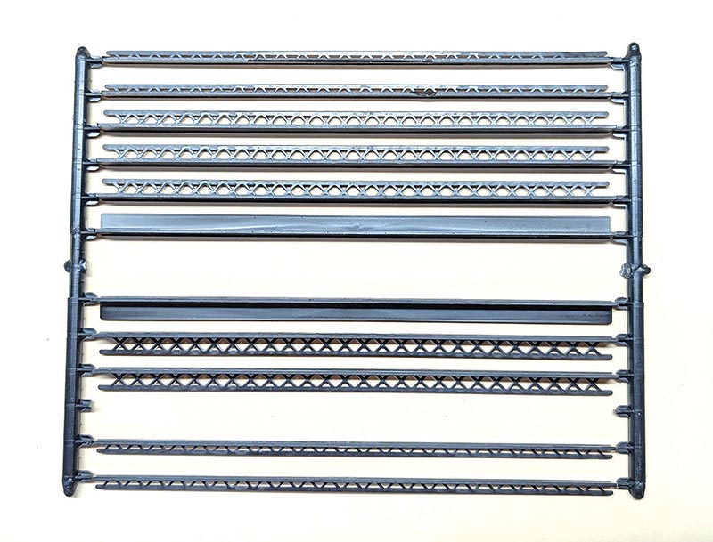
The basis for Gregg’s road bridge was a package of Central Valley bridge girders.
Top Girders
I determined the top girder of the bridge would be the length of one of the “kit” girders, with ends cut off at 45 degrees at an “even” point between X-braces. The end girders that angle down to the base girder were of a length I determined by eye to make a good height for the bridge. I cut the angles at the end of the top girder at 45 degrees and left the end of the sloping girder square. Sure, both angles should have been 22.5 degrees to add up to 45 but I chose the method that would “keep things moving!” I thought that a square plate would make the joint good and used .020” plain styrene sheet. Plastruct Bondene was used for minor glue joints, but I’m of the old school—real old school—and I still prefer Testor’s Cement for plastic models for most applications. That’s the stuff in the red squeeze tubes that everybody calls “model airplane cement.”
Bottom Chord
Length of top girder plus angled end girders resulted in 60-scale-feet for the bottom girder. What to use for that? Maybe it should be an I-beam or maybe another lattice girder. I didn’t know and I didn’t care because it’s painted dark colors and exists beneath the roadway. All I cared was that the top edge of the bottom girder be the width of the angled end girders that attach to it. A search through my parts box found that a double thickness of Evergreen HO Scale 2×8 strip stock would give what I wanted. I thought that the double thickness for the entire length of the bridge wasn’t necessary, so doubled up the 2x8s for only three feet at each end. I then glued the bottom piece to the assembly of lattice girders and found that the height of the side truss is 11 feet.
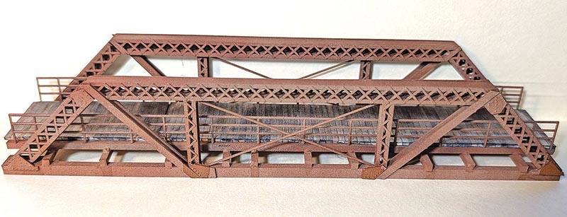
Completed bridge.
Side Angled Bracing
Since the base of the truss is 60-feet long, it seemed logical to place vertical smaller lattice girders at 20 and 40 feet. Double iron straps (plastic parts from the Central Valley package) were placed from the bottom of the small vertical girders at an angle to the junction of the top and end girders. Small reinforcing plates with rivet detail were selected from the Central Valley girder package. Photo 6 shows a completed side and a partially complete side with the Central Valley bracing material ready to be added. After both sides were completed, I drilled holes for wire to represent the round rod that forms an X between the vertical girders…