 By Jack Burgess, MMR/model photos by the author
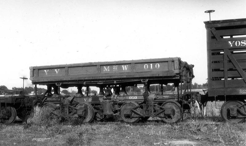
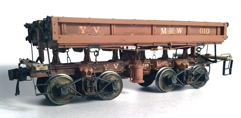
The prototype Yosemite Valley Railroad purchased a new 12-cubic-yard side dump car in 1927 from the Western Wheeled Scraper Company, and lettered it “MW 010.” This car was much like a current-day dump truck although it dumped its load to either side, rather than to the rear. The YV most likely used this car for clearing rockslides in the Merced River Canyon. Hank Johnston included a photo of this car in his very first railroad book “Short Line to Paradise,” which preceded his “Railroads of Yosemite Valley.” The latter included another photo of this car. A few months after deciding to model the YV in 1967, I bought a Model Engineering Works HO scale side-dump car kit, and replaced the metal sides of the kit’s dump body with wood sides similar to those of the YV car. After painting and individual-letter decals, I declared my model “good enough,” and added it to my slow-growing YV equipment roster.
Thirty years later, I finally realized that my earlier model was no longer “good-enough.” The major issue was the size of the air cylinders – they were much too large. Therefore, I rebuilt my earlier effort but, as I got into it, I realized that there were too many compromises to overcome. While I finished the model, I wasn’t satisfied. (Rio Grande Models does sell a kit for a side dump car that appears to be about the same size as the YV side dump, but the mechanism to tip the body is of a different design.
Using 3D Printing
I began using 3D printing to produce detail parts in mid-2013. As I gained experience using SketchUp, I took on more advanced projects. (My article in the September/October 2014 issue of the GAZETTE discussed the use of the free SketchUp software program to produce 3D drawings of needed detail parts.) In late 2014, I finally realized that I could use 3D printing to produce the frame and air cylinders for a model of MW 010. 
The prototype side dump car in the YV’s Merced, Calif., Yards about 1940. Photo by Paul Darrell
With a complex project such as this one, I first prepared scale drawings of the prototype in 2D CAD (computer-aided design) software before I could start drawing it in 3D. I had the overall dimensions of the car, and started from there, estimating other dimensions from the limited prototype photos I had – and using Photoshop to compare known dimensions (such as wheel diameters and axle spacing) to unknown elements.
It was important to also understand how the tipping mechanism actually worked. Kyle Wyatt, Curator for the California State Railroad Museum, was especially helpful, and provided me with a list of patents, which I could download via Google to help in my research. A visit to Jamestown, Calif., to photograph the Sierra Railroad’s side dump cars stored there was also valuable. In addition, I contacted Sierra Railroad and Virginia & Truckee Railroad researcher Mike Collins who sent me a print of his preliminary CAD drawing of a Sierra side dump car. My 2D drafting effort took several months, but once I was satisfied, I started drawing a 3D version of the car using SketchUp.
Design Standards and Testing
Design standards for printing a part or model in Frosted Ultra Detail (the material I planned to use for the model) are set by Shapeways, the 3D printing service bu-eau that I have been using for other projects. Shapeways specifies a minimum prototype thickness of 1.026-inch for a wall supported on two or more sides when printed in HO scale. A “wall” supported on only one side needs to be twice as thick.

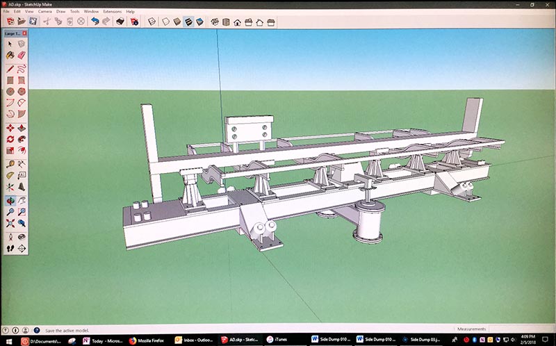
This screen shot shows the basic frame, bolsters, pedestals, air cylinders and the framework supporting the dump body. On the end above the coupler pocket are four pins to locate the end platforms. The spur on top of the body holds a jig for drilling holes in the end platforms. It will be clipped off in the final 3D print.
I wanted the model to be as close to the prototype in dimensions as possible, but I like to “push” these design limitations. The frame consisted of two C channels. I drew just one C channel with a web thickness of exactly 1-scale inch, and uploaded that file to Shapeways.
Once uploaded, Shapeways’ computers test the file to ensure that it meets their design standards. This “testing” process is an important step in designing 3D parts. Their computers will check to ensure that every element of the model or part meets or exceeds the design standards for the selected print material. The computers also check to make sure that the overall size of the model or part is not too small or too large, that wall thicknesses are ad-equate for the printing, and later cleaning processes. The computers also check that the sprues holding multiple parts are large enough, and that all the elements of the drawing are truly connected to each other. This can be hard to see on 3D drawing, but the Shapeways computers have a way of identifying such potential problems.
Uploading a file to Shapeways to test doesn’t cost anything. But you don’t want to spend hours working on a large, complex project only to find out that it can’t be printed due to problems that could have been addressed much earlier, So it is worthwhile to often upload the file for an ongoing project during your design phase. It takes about 10-15 minutes depending on the complexity of the part for the Shapeways’ computers to finish the test. My single C-channel passed the Shapeways tests, and I was ready to continue with my design. From then on, every time I added a new element to my drawing that might be bumping into minimum standards, I uploaded that file to Shapeways to make sure it could be printed…


