 By Sid Tiesenga/photos by the author
Controlling small-scale, live steam locomotives can be tricky. They may stall on upgrades, and often run too fast on downgrades – and, slow switching is hard to achieve. So, I was intrigued by the review on page 12 of the May/June 2016 GAZETTE that described an inertial device (called a Slo-Mo) made in Australia by Small Steam Performance. Slo-Mos were designed to smooth out the performance of small-scale, live steam locomotives. When I viewed the video on SSP’s website, I was amazed at the slow speed control of live steam locomotives equipped with a Slo-Mo. Basically, a Slo-Mo is an axle-driven flywheel system that can be fitted between the frame members of a locomotive. (There is also a Slo-Mo available that fits into a four-wheel freight car.)
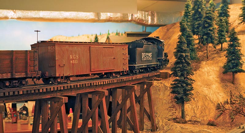
So, I decided to make my own version of a “Slo-Mo,” and fit it into a freight car truck on a 1:20.3 scale boxcar. I hoped that it would improve operations on my indoor live steam layout (see November/December 2012 GAZETTE). Rather than using a set of gears, as the Slo-Mos do, I decided to use a sprocket and chain mechanism. Micro-Mark sells sprockets and chain that can be used. My device, shown here, uses a two-step system employing 20-tooth and 9-tooth sprocket wheels to provide a final drive ratio of 5:1. Coupling the car’s two axles with sprockets and chain provided a “four-wheel drive” for better traction, and I was able to build my device into one freight car truck. 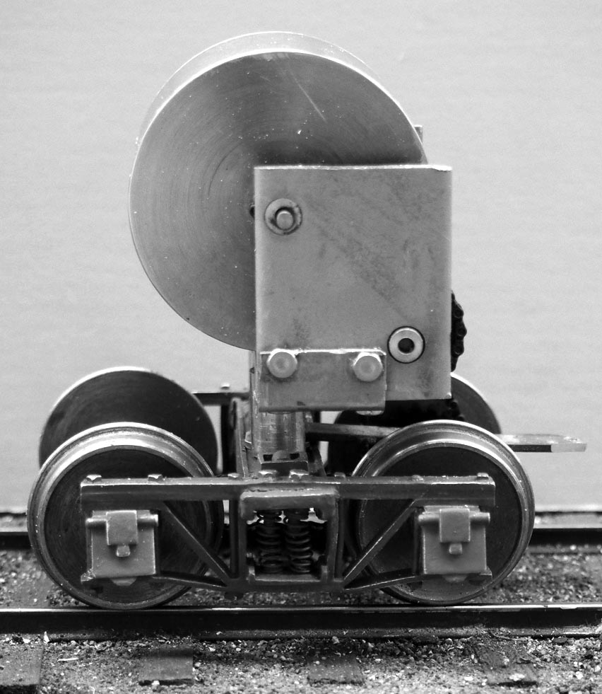
The author’s inertial device mounted in a freight car truck. The 1.5-pound flywheel smooths out the operation of small-scale live steam locomotives.
I started my device by making two, 2.25-inch-diameter axles from stainless steel rod. These axles were turned down to fit the sprocket wheels, and a step-up, or intermediate axle, with two sprocket wheels was also made. I turned down the ends of the axles to 0.125 inches to mount the sprockets on the axles. I then turned bushings, and used them as spacers when remounting the wheels on the now “thinner” axles. I also had to file out a recess in the truck bolster to clear the chain running from one axle to the other.
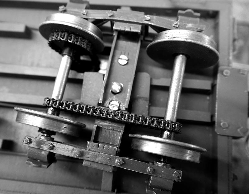
A sprocket chain runs from one axle to the other to provide a four-wheel drive. Note how the bolster has been modified to clear the sprocket chain, and that the truck has swiveled.
Next, I made two side frames for my device. I drilled holes, and fitted bushings, for a 1.5-pound brass flywheel, and for the step-up, or intermediate axle. These two side frames were fitted with two mounting brackets that span the narrowed center sills of a boxcar, and allow my device to be attached to the car, and allow the truck to pivot.
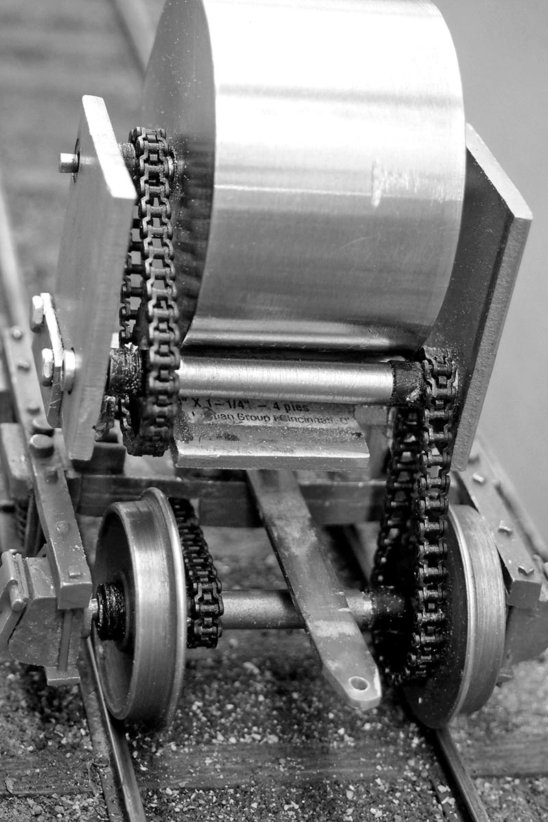
This end view of the author’s device shows the flywheel, step-up or intermediate axle, chain drives, and sprocket wheels. That “tongue” couples into a link-and-pin coupler so the device can be tested behind a locomotive or car.
After narrowing the center sills of the boxcar to fit my device, I cut a hole in the car’s floor for the drive chain. Then I detached the device from the truck, and passed the device, without the truck, through the door of the upside-down boxcar. Then, I re-attached the device to the truck. I found reconnecting the drive chain was tedious, but I did it in a few tries.
I then tested my device, and was pleased with the improved performance of my steam locomotives. This testing also con-vinced me that the Micro Mark chain and sprockets were up to the task – an earlier concern of mine.

This knuckle coupler has been modified to couple with a link-and-pin coupler, allowing the author to test his
device behind a locomotive or freight car.
The resultant improvement in smoothing starts and stops, as well as in speed control on grades using my device was gratifying. But it was less dramatic than the performance of the Slo-Mos that I saw on the Small Steam Performance website. I found that the improvement was most evident with small light locomotives. In use, my device is essentially invisible, even with the boxcar doors open. I did find it useful to add 16 ounces of lead to a boxcar for better adhesion. Oh – and I also modified a knuckle coupler to couple to link-and-pin couplers, allowing me to couple my device to the end of a train during testing.


