

 Larry Tidball/photos by the author
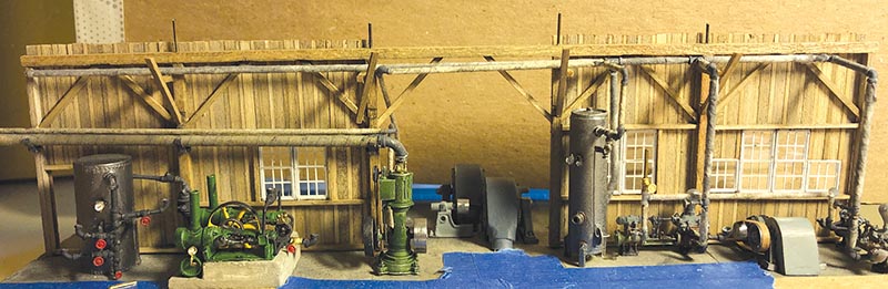
One of the greatest modeling challenges was the extensive piping connecting the boilers, machinery, and sawmill. The 1937 appraisal of WSLCo properties lists piping for all machinery in the mill complex. With some interpretation, I backdated this information to size the piping for the earlier period modeled. The system included steam, condensate-return, feedwater, and compressed-air lines. All but the compressed-air piping would have been insulated, and steam fittings would have had bolted flanges. I needed elbows, tees, unions, and valves for pipe sizes ranging from 2 to 12 inches ID. I used brass tubing for the piping, oversizing it for insulated lines to account for insulation thickness. Valves and fittings came from several manufacturers in HO, S, and O scales, with additional flanged fittings fabricated as needed.
I began the boiler house structure by fabricating the roof trusses in a jig. A 1906 insurance document at the TCHS gives the timber and iron truss-rod sizes. After drawing a plan, I taped it to a work surface, covered it with wax paper, and built the first truss over the drawing. Period interior photos of other WSLCo buildings show mortised connections in the post-and-beam framing, so I followed that practice for the 1900 boiler house. The diagonals are let into the truss’s top and bottom chords, and diagonal braces are mortised into the posts and beams. Before assembly, I made a jig to locate the mortises accurately. Using a microsaw, I cut each end of the mortise, then removed the material between the cuts with an x-Acto knife. A stop on the jig controlled the depth of the saw cuts and guided the knife blade. The trusses’ bottom chords are 60-feet long. Assuming a single timber of that length would not have been available in 1900, I added scarf joints to the basswood bottom chords. After fabricating the first truss over the drawing, I made a styrene jig to match it. I used this jig for the remaining trusses, shimming the smaller diagonal members so they were centered on the larger top and bottom chords. For consistent, tight fits, I cut and sanded the angled ends of the diagonals to final length and angle with an Ultimation Repeater and its hand-sanding disk.
Each long wall of the boiler house supports the trusses. I built the walls with scale post-and-beam framing, mortising the diagonal braces into the posts, truss bottom chords, and the beam running along the tops of the posts. To strengthen the structure, I inserted brass pins between the posts and the Masonite concrete-floor base and between the posts and trusses.
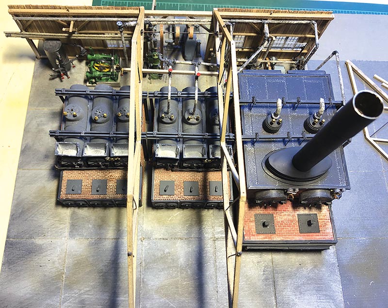
With the boilers in place, I installed the north wall and added the trusses one at a time. Piping supported from the truss bottom chords could then be installed. By working through the open space beside the last truss, I could reach the piping above the boilers.
The boiler house exterior is covered with board-and-batten siding. Rather than use milled basswood siding, I added 4×6 purlins between the posts to support the Simpson Models window castings, as on the prototype. I simulated the siding with individual 2×10 boards and 3×4 battens, applying them over the post-and-beam framing while each wall lay flat on the workbench. This produces the board-and-batten appearance more quickly than applying scale 1×4 battens over every joint between 1×12 boards, and it effectively represents the prototype where the wall interior remains visible. Before fabrication, I lightly distress the basswood, rub in PanPastel Raw Umber and Neutral Grey, and wash the wood with isopropyl alcohol. This effectively stains the wood and keeps the pastel from rubbing off during handling. The resulting variation among individual boards works well for a mildly weathered structure. West Side painted some structures, including this one, with dry red-oxide pigment mixed with linseed oil, which weathered and faded over time. I lightly brushed Red Oxide PanPastel over the completed exterior walls and added darker weathering along the bottoms. The boiler house’s north side adjoined a conveyor area also used to store sawdust and cordwood fuel. I left this wall unsided on the model to give boiler-room workers access to the fuel for hand-firing the boilers.
I began to appreciate the complexity of assembling the boilers, machinery, walls, and roof trusses while fitting all the piping, fittings, and valves. Without HO scale workers inside the structure, installing everything from outside with 1:1 fingers required a plan. I had already drawn the boiler house in AutoCAD, so I converted the drawing to an isometric view and removed the siding, leaving only the posts, beams, and trusses. I added the boilers and machinery, then laid out each piping run, including valves and other equipment. This revealed conflicts among pipes, truss braces, and blower belt drives, allowing me to revise the piping until everything fit.
Only the horizontal steam engine’s location is known with certainty from a prototype insurance plan. The “fan room” projecting from the south wall confirms where the blowers were located. The blowers forced air through a channel below the floor slab and up into the boiler furnaces to create the required draft. The plan also hints that the fan room contained a “pit,” which I assumed was a hot well holding condensed steam returned from machinery for reuse. I placed the remaining machinery logically to minimize piping runs, guided by historic boiler-room engineering books.
With the isometric drawing complete, I planned the final assembly. Work proceeded from the floor upward, fitting as much as possible before installing the trusses. Because the trusses support some piping, however, those runs could not be installed until the trusses were in place. I was able to mount several piping runs on supports attached to the south-wall framing, which simplified assembly.
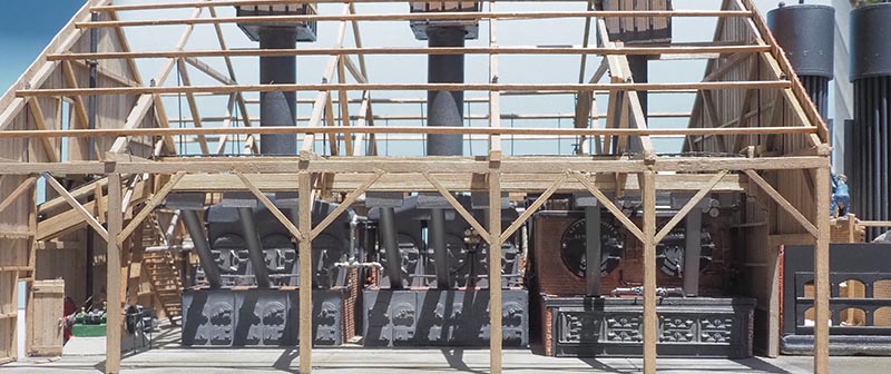
Completed Boiler House.
Photo 2 shows the start of assembly. The machinery is glued to the floor, which is painted to simulate aged concrete and temporarily protected with cardstock. The south wall is in place, and some piping has been installed. Metal wall brackets support large hot-water return pipes from the Corliss engine in the sawmill; the pipes slope toward the hot well, hidden behind the vertical engine. Horizontal timbers connecting the diagonal braces to the wall posts form an upper-level pipe support; the braces will eventually connect to the truss bottom chords. Steam and other hot pipes are wrapped with thin strips of first-aid tape to simulate asbestos insulation, then weathered with a dirty-water wash.
Where possible, I drilled through the pipe fittings and ran smaller-diameter wire or tubing through each valve, tee, or union. I then slipped the correct-size brass tubing over it to represent pipe abutting the fitting. Very small, hard-brass castings were difficult to drill through, so I drilled only a shallow recess and soldered brass wire into the fitting. During installation, I could leave a short wire stub extending from a fitting so the next pipe section could slide over it later. I often had to preassemble two or three pipe sections and fittings before reaching into the model with tweezers to install the assembly, making solid tubing-to-fitting connections essential.
Before installing the boilers, I attached as much piping as possible, including the injectors and gauges at the boiler fronts. I also glued a styrene stub to the top of each Dutch-oven furnace; later, a styrene tube representing the sawdust chute from the conveyor system would slide over it. With the boilers in place, I installed the north wall and added the trusses one at a time. Piping supported from the truss bottom chords could then be installed. By working through the open space beside the last truss, I could reach the piping above the boilers. After that was complete, I slid the boiler stacks, with their attached breeching, between the trusses and anchored them to the roof framing to maintain vertical alignment. Each stack has a cube-shaped thimble where it penetrates the roof framing, protecting the wood from heat. Inside each thimble, I soldered a brass tube one size larger than the stack tube. This allows me to transport the model with the upper stacks removed; for display, they slip into the larger tubes concealed within the thimbles…