

 Glenn Lapkin, MMR
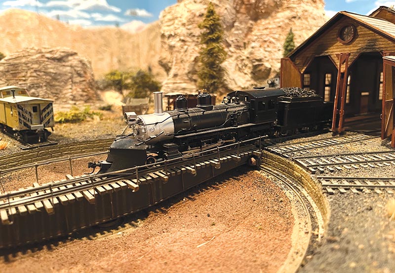
It is clear that the inspiration for the narrow gauge line and the turntable on my Cease and Desist Railroad is based on my interest in Colorado railroading. The historical research into the use of this unique facility has been revealing. Years ago when I was contemplating this feature, I stopped as I do at the nearest hobby shop. In this case it was The Antique Barn (since closed) in Wilson, North Carolina. While checking out, the turntable came up in conversation with another patron who mentioned that such a turntable must have four rails. A separate set for the standard gauge and another for the narrow gauge with a transition track to go from three rails to four. After, I did some research online and sure enough, the four-rail bridge turned out to be correct.
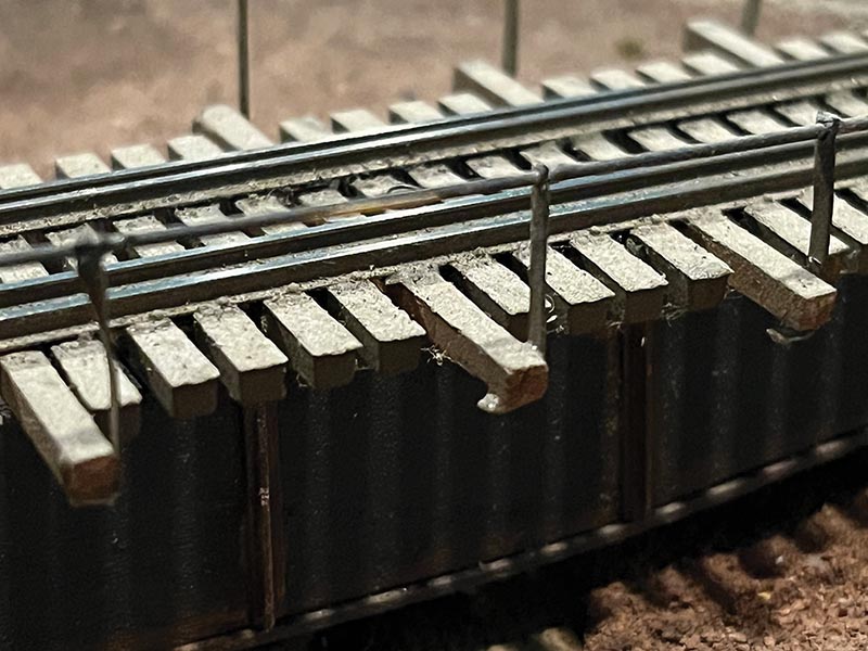
Photo 10
History and Prototypes
Several terminals on the Denver and Rio Grande Western contained both standard and narrow gauge as the narrow gauge came down from the higher elevations to meet the standard. Terminals such as Alamosa (transfer table), Antonito, Salida, and Leadville each had dual gauge turntables. As time went on and the narrow gauge operations were abandoned, many of these yards were converted to all standard gauge.
So why did they need a four-rail con-figuration? The reason for the transition and the four rails is two-fold. The first is that a three-rail setup on a turntable and approach tracks, would reverse the orientation of the narrow gauge track to the other side of the three-rail layout. By centering the narrow gauge within the standard gauge track, the narrow gauge will always be aligned around the turntable. The second and as important, is that by centering the narrow gauge track, the locomotive would continue to be balanced and centered on the turntable. (See Photo 1.)
The color photos are from the Colorado Railroad Museum in Golden, Colorado. You can see the standard gauge and narrow gauge track running in parallel towards the turntable in Photo 2. Photo 3 is a picture of the approach track to transition from three rail dual-gauge to four-rail approaching the turntable.
This track actually has a throw bar, but others are without and use a guard-rail to transfer the path of the locomotive. (See Photo 4.)
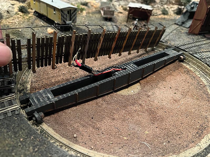
Photo 8
The Model, Mechanism and Wiring
There are several aspects of the turntable that have worked very well. The first is the solid construction of the bridge, the mechanism/wiring of both the rails and the turntable motor and the approach tracks in this dual gauge con-figuration. I would recommend building the bridge first, then cut the pit to fit.
The Pit
Nothing out of the ordinary here, though the pit was cut from a piece of 1/2-inch thick Homasote, 10 inches in diameter, on top of another piece, but with a diameter of only 91/2 inches. The 91/2-inch piece of Homasote was layered on top of 1/2-inch thick plywood. The “shelf” created by the small 10-inch Homasote is where the ring-rail is placed. The area between the ring-rail shelf and the plywood is filled with plaster and sloped to-ward the center of the pit as in the prototype. The wall was lined with embossed plastic stone sheet which does not add too much thickness. At the dead center of the pit will be in-stalled a 1-inch long flanged bearing through which the shaft will go. A broader area around the shaft was formed with a rubber washer during the plaster shaping to create a depressed and flat center pit base.
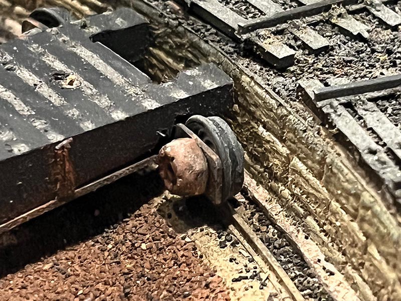
Photo 7
The Bridge
The superstructure is 69 scale-feet long and is comprised of two main girders cut from basswood and trimmed with angle stock representing riveted panels. Between the main girders are spacer blocks, one in the center and one at each end. Refer to Fig. 1 for the exact dimensions and placement.
Once the main structure is built, the turntable wheels must be added at each end. The wheels are just extra plastic wheels, but attached to custom-made brass bracket (see Fig. 1 diagram) fabricated with some elongated holes for minor height adjustment. The connectors used for the wheel assembly are 2-56 x 1/4˝ Socket Head Cap Screws w/lock nut, which represent a wheel mechanism. (See Photo 7.)…